Making movements
Introduction
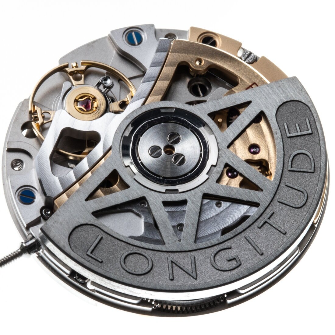
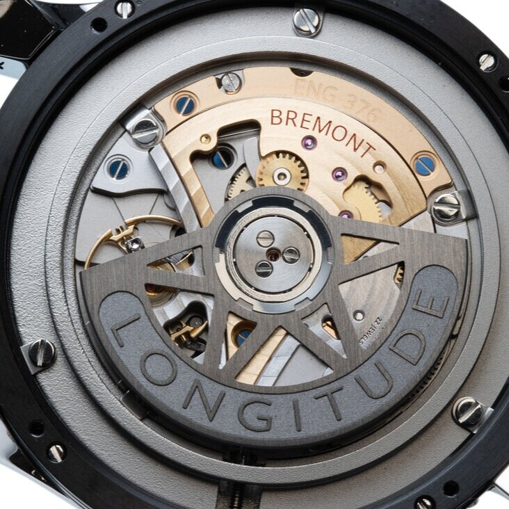
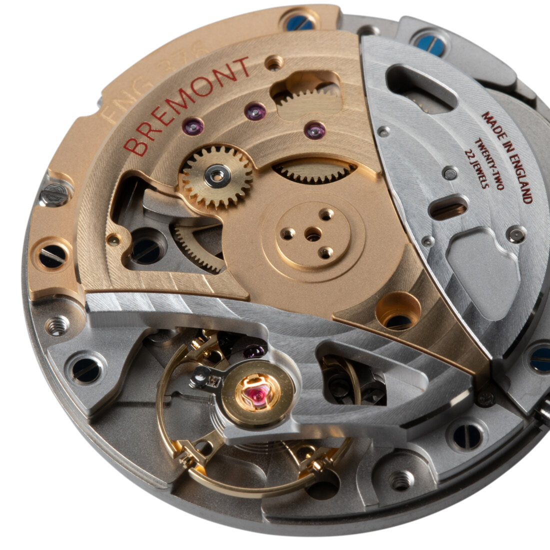
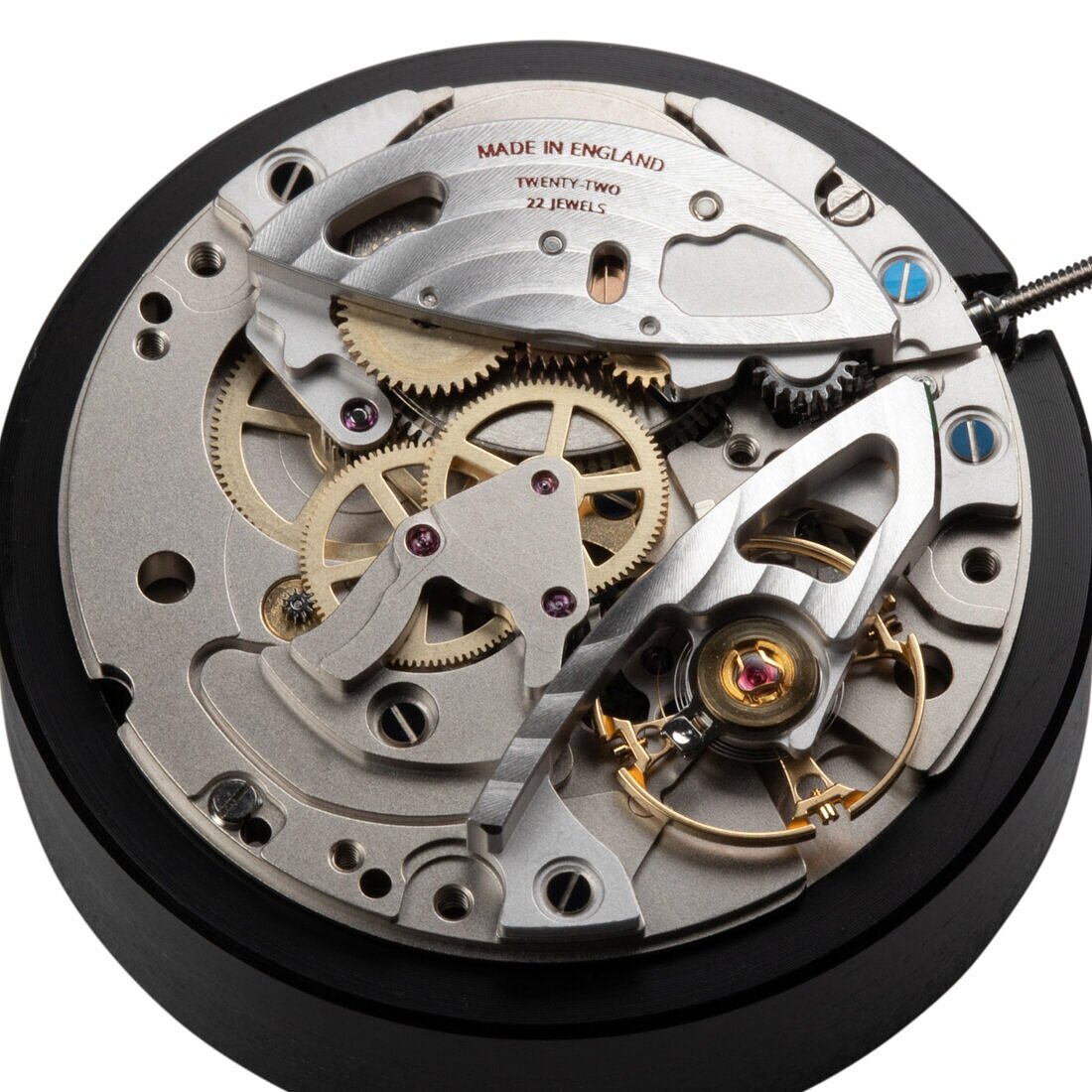
The ENG300 movement series is based on the non-industrialised Swiss K1 movement developed by THE+ over a seven-year period. Bremont purchased the design and production rights of this Swiss calibre, re-engineering it over an additional two years to their own specifications with the support of the Swiss team to manufacture it in the UK. The calibre shown below is the ENG376.
Their first step in the manufacturing strategy of an industrialised calibre on UK soil is the production of the main-plate, (the base upon which all bridges and components sit) as well as the bridges. Followed by all assembly and adjustments required to finish the movement. The long term strategy is to develop and integrate the maximum number of components needed in a mechanical movement to be made within the Bremont facility.
When producing small numbers of watches the process of movement development can be considerably faster. Making large industrial volumes is a complex process requiring analysis and repeated testing at every level prior to implementation.
technical Specifications
Diameter: 25.6mm
Thickness: 4.95mm
Power reserve: 65 hours
Frequency: 25200VPH: (3.5Hz)
Balance wheel and spring: Timing screws on balance rim (free-sprung), flat balance spring
Escapement: silicon, variation of a Swiss-lever
Jewels: 22
Power reserve: Indicator at 6 o’clock
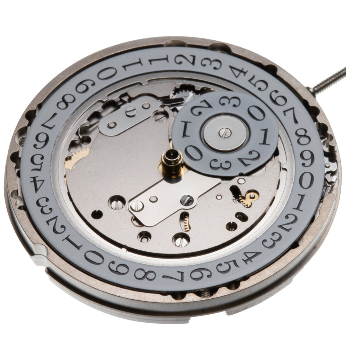
Calendar: Option of convention date disc or larger double-disc indication (shown here)
Seconds indication: Offset seconds hand at 9 o’clock or central options
Automatic winding: Uni-directional
Oscillating rotor mass material: Full tungsten
Variations
The thought process behind the ENG300 series was to develop a mechanical movement with modular flexibility, the ability to make diverse variations of timepieces on a single foundation. The basic movement can be changed into diverse calibers in addition to the inclusion of future complications. The design allows for either off-set seconds at 9 o’clock or central seconds (or none), conventional calendar size indication or a larger twin-disc system (or none), a power reserve indicator when needed, either automatic or manual wound versions.
Design
Although the original basic calibre was Swiss in design it has been adapted stylistically and technically to follow the brand’s philosophy. The design of the bridges is unique to Bremont and follows the profile of an aircraft’s wing. The colour combination of rhodium and 3N yellow gold is a mix of Swiss and English. Many Swiss movements are plated with Rhodium, a hard and bright plating that accentuates decoration, and 3N yellow gold is traditionally the gilded finish found in early English pocket watches and marine chronometers.
development
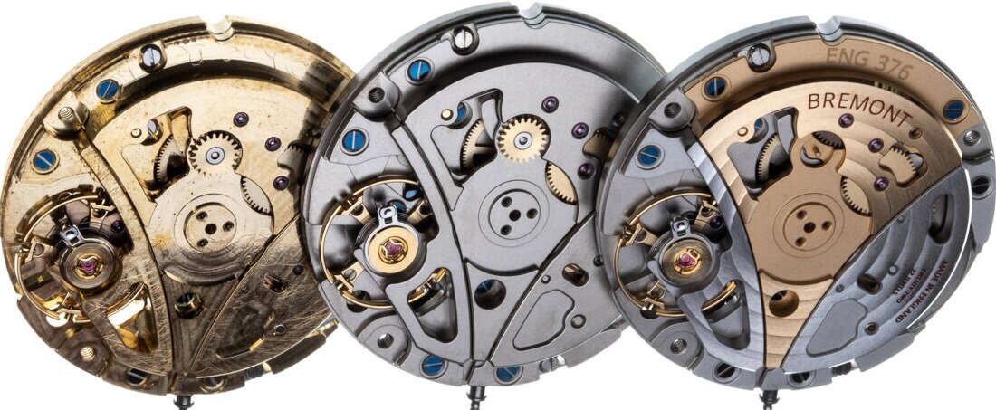
On the left, one of the first prototypes that were used to validate the assembly of the new construction of the calibre with parts produced at the Wing and the practical functioning of its mechanisms. The centre version partly decorated and is used to continue the testing process. On the far right, one of the first finished examples with the definitive decoration to be used on the -Longitude- model.
Technical changes
The technical changes below were made in order to increase the overall strength of the movement, below are some of the modified elements.
The number of case clamps holding the movement in the movement ring and case was increased from 2 to 3, a small detail but affecting the overall design of the main plate and the surrounding bridges.
The lower automatic bridge was broadened and the jewel size increased in diameter to strengthen the overall construction and facilitate assembly.
The steel wheel assembly transmits power from the rotor via a small pinion. The steel spring to the right prevents the wheel from turning backwards when it is under tension from the mainspring.
The original balance cock that held in place the balance assembly was screwed down from one side has been replaced with a bridge holding the balance assembly in position from both sides, strengthening the overall construction.
The original regulation system for the balance spring was replaced with a ‘free-sprung’ balance wheel. (A free-sprung balance is regulated by adjusting timing screws that are set into the rim of the wheel, a system found on many high-end calibres.)
The silicon Swiss lever went through over 14 modifications until it was validated. The reason for the length of time taken in this process was the fixed nature of the escapement.
Unlike traditional escapements that allow for adjustment, the use of a silicon escape wheel and lever means less sliding friction and can not be magnetized, but can not be adjusted once made. Therefore, the design has to be as near to perfect as possible, as does the precision of the main-plate and bridges that hold it in place.
Modification to the original canon pinion clutch system to assure longevity and increased smoothness of the setting of the hands, through the addition of 4 lazer cut springs instead of the original crimped system that was previously used.
Dismantling the movement
The rotor weight removed, held in place by 3 screws, pivoting on a steel bead ball race.
The rotor weight made from a single piece of tungsten carbide.
The automatic bridge removed showing the normally hidden going train.
In total there are 3 sizes of screws. All of the bridge screws are the same size in order to simplify assembly and production. After which there is a specific size for the rotor weight and another for the calendar mechanism.
The movement held in a tailor made movement holder that in turn fits onto a carousel system for volume assembly.
Underside of the automatic bridge showing the auto-gear train transmitting power from the rotor through to the barrel.
The gear train (going train) leading power to the escapement, the balance wheel assembly with bridge removed.
To the right the small steel spring is the “hack” or “brake” for the balance wheel (usually held in place by the balance wheel bridge) meshes with the setting mechanism, it is activated when the winding crown is pulled into the setting position stopping the balance from oscillating to allow the second’s hand to be set to the correct second.
Recto-verso of the balance wheel and bridge assembly
The central shock protection for the balance wheel pivots is -Kiff-. The balance pivots are the most delicate in a wristwatch, in relation to their diameter and the mass they carry in the form of the balance wheel.
The small cut-outs that are seen on the edge of the balance wheel were made when material was removed as the balance was poised to ensure there were no uneven heavy spots on the balance wheel.
The timing screws are adjustable, held tightly in place by the split hole they sit in. The split acts as a spring holding the timing screws in place.
The escape wheel and lever with and without the escapement bridge in place. The sliding frictional contact between the teeth of the escape-wheel and the Swiss anchor/lever escapement is less than that found with the traditional jewel and steel contact. Tests in Switzerland have validated this phenomenon.
The screws are heat-treated to create the blue. The only surface blued is the flat top because it is the only part of the screw that is re-polished after it is nickel plated.
The train bridge removed with the train wheels still in position.
In order to have the choice of either a centre-seconds or, off-set seconds indication at 9 o’clock the below assembly (shown in drawings) sits to the left of the lower central wheel. The large upper wheel turns once a minute, and drives the escape-wheel (the blue silicon wheel). This lower central wheel drives both the upper wheel leading to the escape-wheel and in turn to the escapement impulsing the balance, as well as driving the small pinion to its lower left.
A cross section of the assembly. When the seconds hand is pushed onto the axel/pivot the large section below it pushes onto the lower blue surface.
The small circular spring takes up any play between the pinion teeth and the wheel that drives it. The hole in the side of the blue coloured tube allows for cleaning liquid to pass through when the movement is cleaned.
The small pinion turns once every sixty seconds and drives the axel that carries the offset second’s hand. When the same movement is used but with a central seconds hand, this assembly is not added to the calibre.
The going train removed leaving the barrel bridge in place.
The barrel bridge removed showing the full view of the barrel.
The barrel bridge. On the underside view of the bridge the gear to the right is linked to the automatic winding mechanism. The gears to the left mesh with the manual winding.
Production
As mentioned in the opening paragraphs the first stage in the development of the production of the movements in the UK begins with the manufacture of the main plate and bridges plus the fitting of the jewels. Following this, the decoration and plating are executed in Switzerland before returning to the UK for the final assembly, controls, and tests leading to the casing up of the finished movements.
The main plate and bridges are made by the below machine Micro 5. A five-ax compact, new generation milling machine.
The brass plates are a standard size made to fit to the steel support.
The plates are manually bolted onto the steel support in preparation for machining.
The plate in position on the Micro 5 about to be machined.
Both the machining head and the base the plates are held on, move during the machining process.
Once the main-plate is machined it is manually removed from the outer square. The last cut of the milling, cuts the circular slot defining the largest diameter around the main-plate and leaves in place the small links to the original material. The links are weak enough to simply be pushed out as the final process with in the plate.
Once the machining is finished on the Micro 5 all of the milled out dimensions are then compared with the original drawings in order to validate the precision of the final pieces. The machine below performs this stage.
Variations in machining can be caused by multiple factors, ranging from imperfections in the original material, cutters and drills that are worn or broken to variations in temperature or movement of the plates on the machine itself.
Below is an example of the automatic bridge machined but still in the brass plate, sitting on the plate below the optic sensors.
The above automatic plate is viewed through a lens and each hole is measured and compared with the original program. The green indications are all within a tolerance of several microns. The red dimensions indicate the hole drilled is outside of the set limits. In this particular instance, the bridge can be accepted because the hole is nonfunctional, it is a window to access visually a jewel that is set into another bridge below this one.
On occasions to validate holes that have failed the visual test, they are checked a second time manually using precision gauges accurate to microns.
Additional tests are made manually to several microns on vertical posts on the machine below. Presently during the development process and first production series of the movements, the parts are checked 100%, meaning that every part and its dimensions are validated. Once the production is fully validated and large volumes are being made, the number of checks will reduce.
Once all of the dimensions of the main plate have been verified, the small triangular sections that held it into the outer plate are machined off manually.
Below are the pieces that are machined using the Micro 5. The milling machine cuts the form on both sides of the plate. The smaller the part the more that can be machined on a single plate.
After the pieces are machined, they undergo a process that removes the majority of the machining marks left from the Micro 5. On the right, the part is straight from the milling process. Steel pins are placed in a solution of liquids that are then activated by a rotating magnetic plate.
The parts are then struck within the solution for a predefined period of time, by the magnetised steel pins removing the machining marks without damaging the bridges and main plates.
2022 includes integration into the UK facility of the following elements:
(T0 to T3 are terms used in the Watch Industry to describe the different assembly stages of a wristwatch. T-zero (T0) pre-assembly of bridges, main-plates, and small components. T-one (T1) assembly of the movement with parts usually dismantled for the cleaning process, and final adjustments. T-two (T2) casing up of the assembled movement with the dial, hands, and placed in the case. T-three (T3) adding the bracelet or strap, and buckle, presentation box, and certificates, etc)
T0
Pillar insertion into the upper date plate
Fixing the balance spring into the stud
Assembly, riveting and pressing of 39 components/processes
Assembly of the offset seconds mechanism (6 parts)
Assembly of the differential for the power reserve (8 parts)
Assembly of the barrel (4 parts)
T1
Barrel bridge sub-assembly
Assembly of the automatic bridge and rotor
Assembly of barrel bridge
Calendar mechasism components
GALLERY
In the grid below are both images used in the description of this page, plus more. Please click on the image to enlarge and see in full.
To learn more about Bremont

